
Using two high-resolution (0.5 m/pixel) LROC NAC images (M114064206L and M111708164L) taken from two separate orbits (1943 and 1596, respectively), we form a stereo image pair for 3D measurements at the Apollo 14 landing site. Thanks to the high image resolution of the LROC NAC cameras, among the visible objects are the descent stage of the Apollo 14 lunar module Antares, the ALSEP (Apollo Lunar Surface Experiments Package, west of the Antares), a rock nicknamed Turtle Rock (north of the Antares), and multiple astronaut traverse footpaths clearly indicated by disturbed soils. Photogrammetric data processing methods can be used to identify the objects and measure their sizes and shapes. Such information can then be employed to reconstruct 3D models of the objects, which are displayed on the digital terrain model (DTM) of the site that is automatically generated from the same data set. Additionally, one can see Cone Crater at the northeast end of the astronaut traverse.
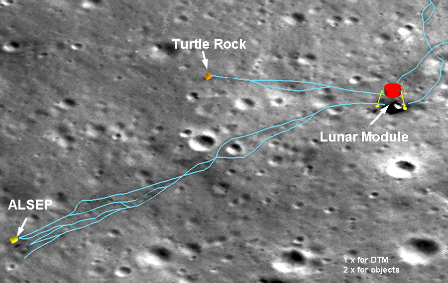
In the zoomed image below, the lunar module can be identified by its deck (red points) and distinctive shadow (green lines). These points are measured in the two stereo images and their corresponding 3D ground coordinates are computed. Note that the shadow analysis uses different times and sun angles of the two images for computation. In addition, the nearby terrain is measured at the selected points on the ground (green points) as a reference. From these measurements, we can compute the height and diameter of the lunar module. As the result, the height of the lunar module (descent stage) is estimated as 3.0 m, compared to the design specification of 3.2 m. On the other hand, the shadow analysis resulted in a height of the lunar module of 3.2 m. Furthermore, using a least squares fitting to a circle the diameter of the lunar module is computed as 4.4 m, compared to the design data of 4.2 m.
 Figure 2. [NASA/GSFC/ASU/OSU] | 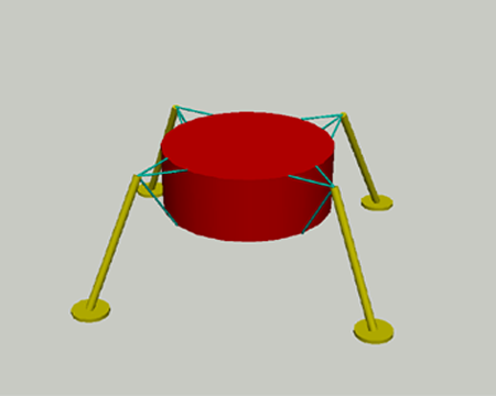 Figure 3. [OSU] |
ALSEP and Turtle Rock are relatively small in the vertical direction. The LROC NAC image resolution and the imaging geometry would not be able to resolve for a height that is less than 1 m. However, we can measure their horizontal dimensions: 2 m x 1 m for ALSEP (yellow points, below left), and 1.5 m x 1 m for Turtle Rock (green points, below right).
 Figure 4. [NASA/GSFC/ASU/OSU] | 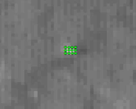 Figure 5. [NASA/GSFC/ASU/OSU] |
Based on the above 3D photogrammetric measurements and the additional information from the design specifications, we created 3D models of the selected objects of the landing site in the AutoCAD system. We then imported these 3D object models into ArcGIS to combine the 3D models with the DTM of the landing site. Generally, a CAD package for 3-D modeling (e.g., AutoCAD or Google Sketchup) and a GIS package (e.g., Autodesk 3D Map or ArcGIS) can be employed for the visualization purpose in this case.
Explore the Apollo 14 landing site in NAC frame M114064206L. View previous LROC releases of the Apollo 14 site here and here.
Published by Jordan Lawver on 29 January 2010